
Signal to Optical Bridge
- Brand: Resonexus
- Product Code: MOS_SW_BRG
- Tariff No: 8537.10.91.70
- Country of Origin: Norway (NO)
- Availability: In Stock
-
€350.00
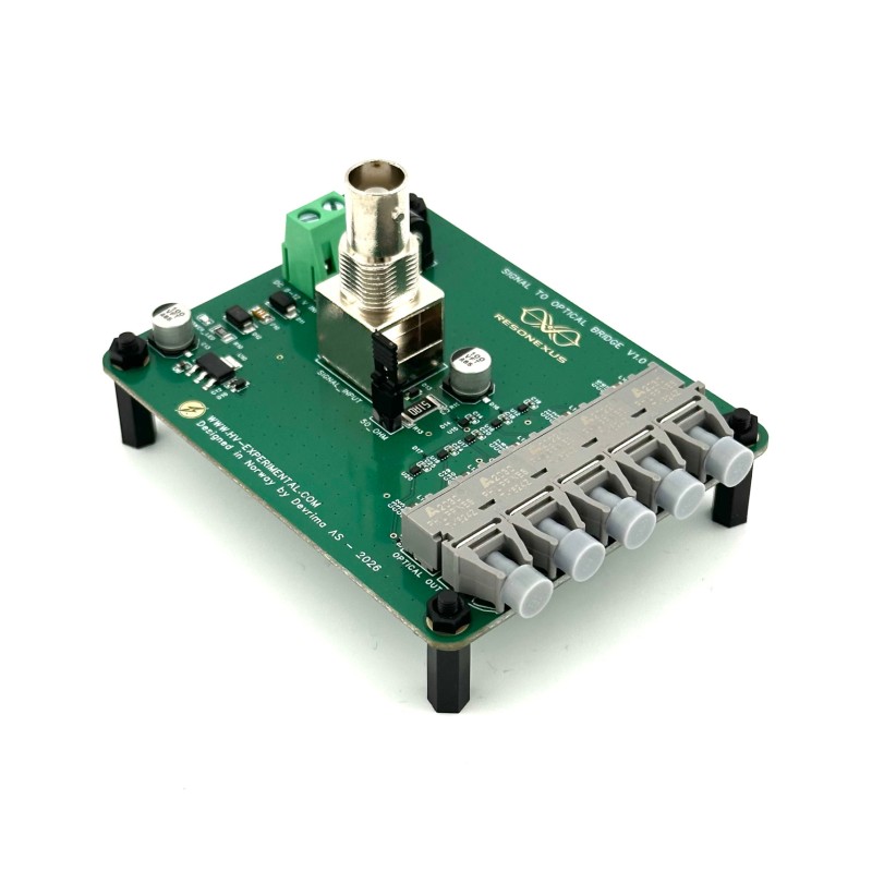
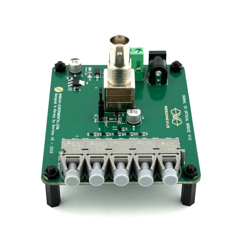
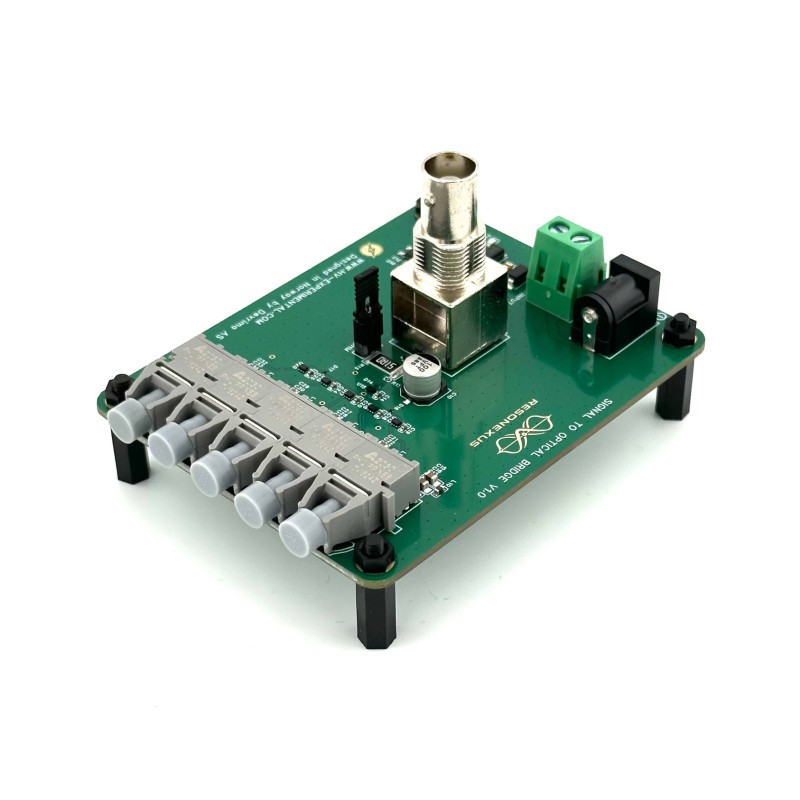
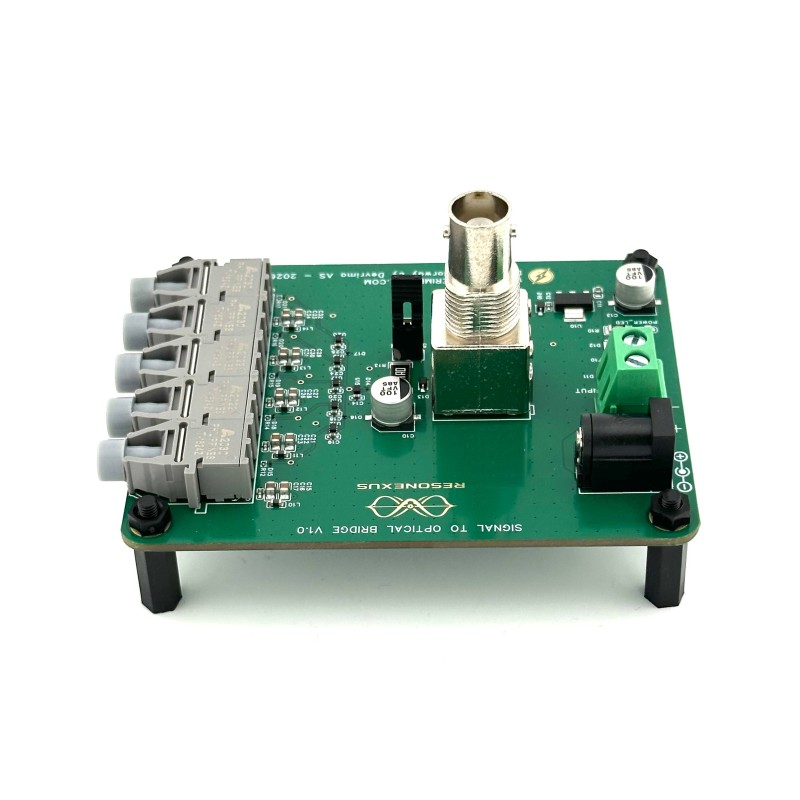
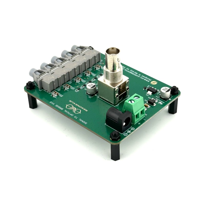
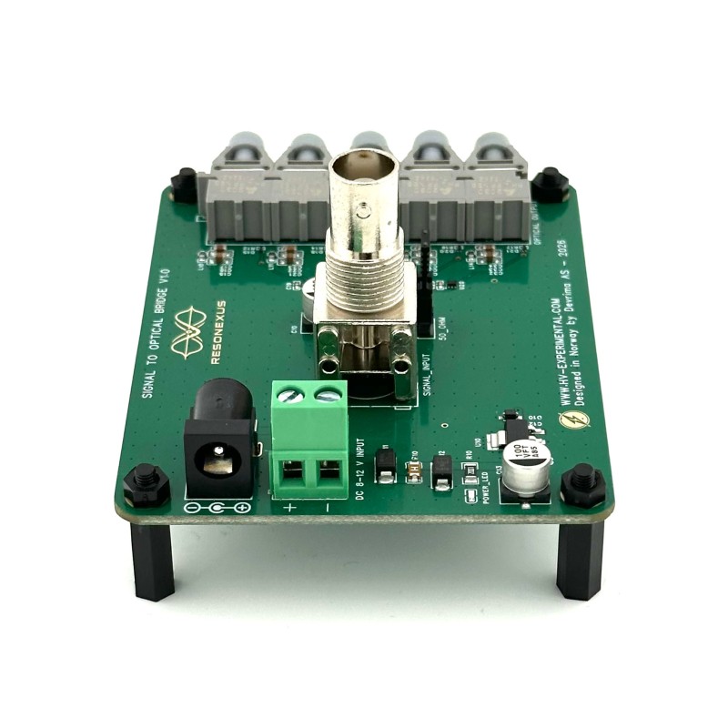
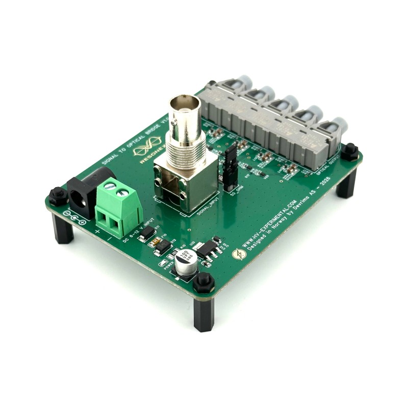
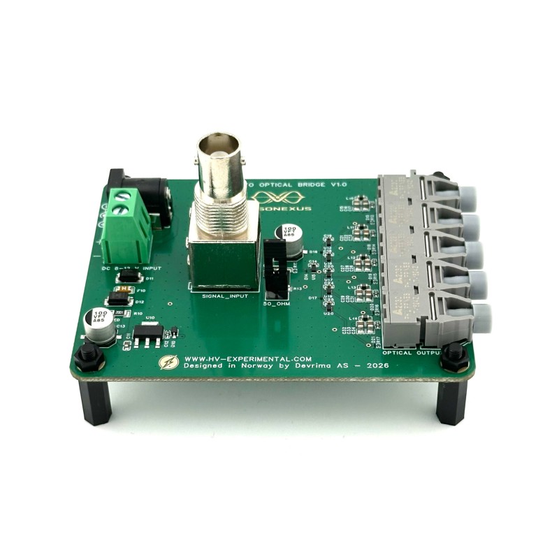
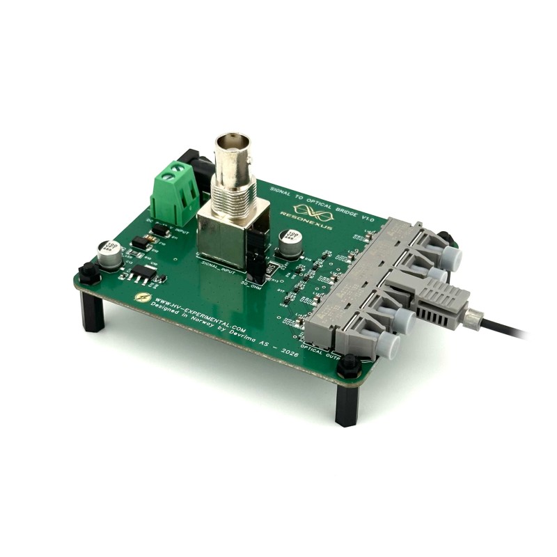
Convert a standard low-voltage control signal into multiple synchronized fibre-optic trigger signals with our Signal to Optical Bridge. Designed for use with our Stackable High Voltage MOSFET Switch system, the bridge accepts a conventional electrical input through BNC and distributes the signal to up to five optical outputs, allowing multiple high-voltage switching stages to be triggered simultaneously while maintaining galvanic isolation between the control electronics and the floating MOSFET stages.
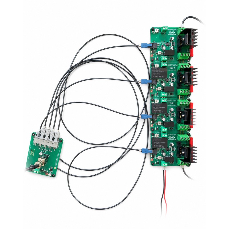
The bridge forms the low-voltage control interface for the complete stacked switching system. A function generator, pulse generator, MCU, or other suitable logic source connects to the BNC input, while fibre-optic cables carry synchronized trigger signals to the individual MOSFET switch boards. Because the optical fibres are non-conductive, the MOSFET stages can operate at very different electrical potentials without creating an unwanted electrical connection back to the control source.
- Up to 5 Synchronized Optical Outputs: One electrical input signal is distributed to as many as five fibre-optic outputs, allowing a complete stack of up to five MOSFET switch boards to be triggered from the same source.
- Designed for Stacked High-Voltage Switching: The bridge is the required signal interface for our Stackable High Voltage MOSFET Switch system. Each optical output connects to one MOSFET switch stage, allowing all stages to receive closely synchronized commands while remaining electrically isolated from the bridge and from each other.
- 3.3 V and 5 V Logic Compatible: The BNC input accepts standard 0–3.3 V or 0–5 V square-wave logic signals, making the bridge compatible with most function generators, pulse generators, microcontrollers, and digital control systems.
- Standard BNC Input: A standard BNC connector provides convenient connection to laboratory signal generators and pulse sources.
- Selectable 50-Ohm Termination: An onboard 50-ohm termination jumper allows the input to be matched to standard 50-ohm laboratory signal sources. When driving the bridge from an MCU or other high-impedance/low-current logic output, the termination can be removed.
- Galvanically Isolated Optical Triggering: Fibre-optic transmission avoids the voltage-reference problem that occurs when several MOSFET switch boards operate at different high-voltage potentials. The optical link carries the switching command without carrying a DC voltage reference between the control electronics and the switching stages.
- Closely Synchronized Outputs: The bridge is designed to minimize channel-to-channel timing differences. When used with equal-length fibre-optic cables and our matched stacked MOSFET switch boards, the complete system can maintain extremely close switching synchronization between stages.
- Fast Signal Path: Typical propagation delay from the electrical input on the bridge to the MOSFET gate in the connected switch board is approximately 85 ns. Typical maximum pulse-width distortion through the complete signal path is approximately 7 ns.
- Flexible 12 V Power Options: The Signal to Optical Bridge operates from a standard 12 V DC supply. It can be powered directly from your own suitable 12 V DC source through the onboard power connection, or with our optional 12 V Power Adapter for a simple plug-and-play setup.
- Separate Low-Voltage Control Domain: The bridge is powered independently from the MOSFET switch stack. This allows the bridge, function generator, and other control electronics to remain on the low-voltage side of the system while only the non-conductive fibre-optic cables extend toward the high-voltage switching stages.
Why Use Fibre-Optic Triggering?
In a series-connected high-voltage MOSFET stack, each switching stage sits at a different electrical potential. The voltage difference between the lowest and highest stages can reach many kilovolts. A conventional electrical signal connection between the control system and every switching stage would therefore be difficult to isolate and could create unwanted current paths, ground loops, or excessive stress across the signal interface.
The Signal to Optical Bridge solves this by converting the electrical control signal into light. Fibre-optic cables are electrically non-conductive and do not carry a DC potential offset, allowing each MOSFET stage to float at its own local voltage while still receiving the same synchronized switching command.
Fibre Optic Cables
One compatible fibre-optic cable is required for each optical output that is used. For stacked MOSFET operation, all fibre cables should have the same length, normally 1 m, to minimize propagation-delay differences between stages. Compatible 1 m fibre-optic cables are available separately or as selectable options with the MOSFET switch boards.
Equipment Placement
Fast high-voltage switching can generate strong electromagnetic transients. The Signal to Optical Bridge, function generator, low-voltage power supplies, and other control electronics should therefore be positioned as far from the high-voltage switching area as practical while still maintaining safe, natural bends in the fibre-optic cables. This helps reduce the risk of interference, resets, or power disturbances in nearby low-voltage equipment.
Typical Applications:
- Control of stacked high-voltage MOSFET switches
- Synchronized triggering of multiple isolated switching stages
- High-voltage pulse generation
- Pulsed-power experiments
- Spark-gap triggering systems
- Plasma and discharge experiments
- High-speed isolated signal distribution
- Laboratory systems requiring galvanically isolated optical triggering
Technical Specification:
| Supply Voltage | 12 V DC |
| Input Signal | 0–3.3 V or 0–5 V Square Wave |
| Input Termination | Selectable 50 Ohm |
| Optical Outputs | Up to 5 synchronized channels |
| Optical Connection Type | Versatile Link, 1 mm POF |
| Optical Wavelength | 650 nm |
| Recommended Fibre Cable Length | 1 m, equal length for all channels |
| Input-to-MOSFET-Gate Propagation Delay | Typ. 85 ns |
| Pulse-Width Distortion | Typ. 7 ns max |
| Maximum Frequency | >10 MHz* |
| Rise Time | Typ. 5 ns* |
| Fall Time | Typ. 5 ns* |
| Minimum Input Pulse Width | 27 ns* |
*The Signal to Optical Bridge is capable of transmitting signals considerably faster than the maximum switching speed of the connected Stackable High Voltage MOSFET Switch boards. When used as part of the complete stacked switching system, the maximum operating frequency and minimum usable pulse width are therefore primarily limited by the MOSFET switch boards rather than by the optical bridge. Refer to the specifications of the selected MOSFET switch board for the applicable switching limits.
Important: The Signal to Optical Bridge is designed to remain on the low-voltage control side of the system. Keep the bridge, signal generator, and associated low-voltage equipment physically separated from high-voltage wiring, spark gaps, and high-current discharge paths. Use equal-length fibre-optic cables for synchronized stacked operation and verify the actual BNC input voltage before applying high voltage to the switching system.
The Signal to Optical Bridge provides a simple and precise way to control multiple floating high-voltage MOSFET stages from a single conventional signal source. With up to five synchronized optical outputs, 3.3 V and 5 V logic compatibility, selectable 50-ohm termination, flexible 12 V power options, and fast timing performance, it is the central control interface for our Stackable High Voltage MOSFET Switch system.
| Technical | |
| Input voltage | 12 V |
| Input signal | 0 - 5 V Square Wave |
| Max frequency | > 10 MHz |
| Rise time | Typ. 5 ns |
| Fall time | Typ. 5 ns |
| Minimum input pulse width | 27 ns |
| Input to output propagation delay | Typ. 85 ns (from bridge to Mosfet gate) |
Related Products
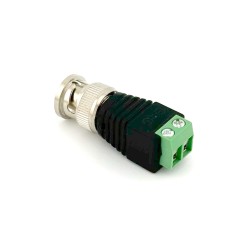
BNC to hookup wire adapter
Our BNC to Hookup Wire Adapter provides a reliable connection between BNC-equipped boards and MCUs o..
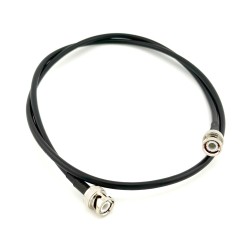
BNC Cable 1m (Female to Female)
Efficiently connect your equipment with our 1m BNC cable, designed for easy connection between your ..
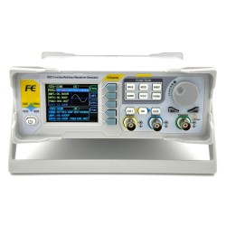
Arbitrary Waveform Generator (60MHz Dual Channel)
Experience the power and flexibility of the 60MHz Dual-Channel Arbitrary Waveform Generator—a must-h..
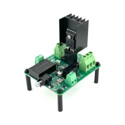
Stackable Mosfet Switch Board (Optical Input)
Take high-voltage switching beyond the limits of a single MOSFET with our Stackable MOSFET Switch Bo..
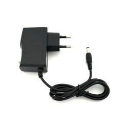
Power Adapter (12V DC - 1A)
Compact and reliable 12 V DC power adapter designed for powering electronic boards, controllers..
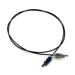
Fibre Optic Cable (1m)
This 1m fiber optic cable is intended for reliable signal transmission between our Signal to Optical..